Transfluid and Addison McKee Link
This function requires that you have a separate license ("Transfluid Interface" or "AddisonMcKee Interface") for it and that "Transfluid Interface" was selected when installing CADMATIC.
You can generate production files for Transfluid and Addison McKee bending machines. Files can be generated for an isometric drawing or for spools. Generating the files again overwrites existing files with the same name.
Optionally, the program can generate cutting lists that contain the information on the cuts and the bends of the processed isometries or spools. Also these files are overwritten on repeated runs.
Defining link settings for isometric drawings
These settings must be defined before generating Transfluid or Addison McKee files for isometric drawings.
Do the following:
-
Do this if managing isometric drawings in Piping Isometrics & Spools:
 Show/hide details
-
In the CADMATIC desktop, browse to your workspace folder, select the Piping Isometrics & Spools application, and select Object > Settings.
-
Right-click the application window and select either Setup TF and AM Link or Settings > Miscellaneous Settings > Define.
The Transfluid & AddisonMcKee link 2.2 options dialog opens.
-
-
Do this if managing isometric drawings in Plant Modeller:
Show/hide details
-
Select File > Settings > Shared Settings > Documents > Isometric Drawing > Miscellaneous.
-
In the Miscellaneous Settings dialog, select the Transfluid & AddisonMcKee link option and then Define.
The Transfluid & AddisonMcKee link 2.2 options dialog opens.
-
-
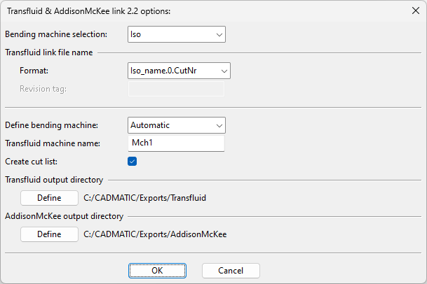
Define the settings:
Show/hide details
-
Bending machine selection – Select whether to generate files for an isometric or spool. (This is only available when defining the settings via the Piping Isometrics & Spools application.)
-
Format – Select how Transfluid files should be named:
-
Iso_name.0.CutNr
-
Iso_name-spool-Bend
-
Idn-spn2d-Bend-rev
-
-
Revision tag – If the naming format includes revision, enter the tag that contains the revision number.
-
Define bending machine – Select the machine type:
-
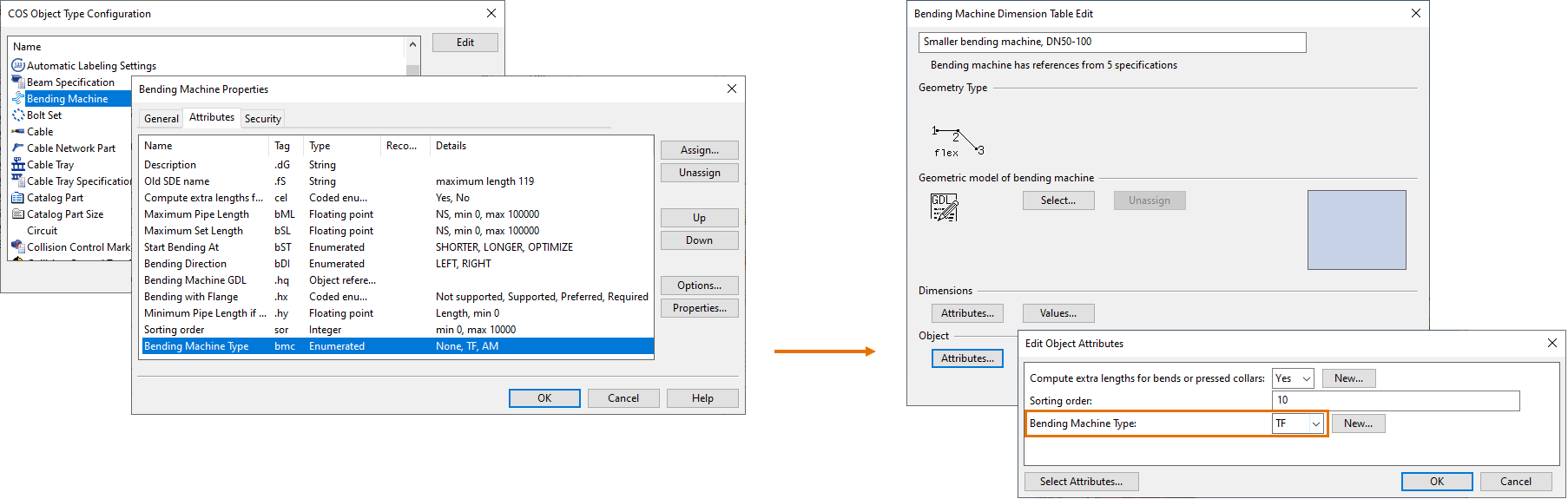
Automatic – This setting allows the machine type to be checked from the attributes of the bending machine: each bending machine should have an attribute whose tag is "bmc" and the value is either "TF" (for Transfluid) or "AM" (for Addison McKee). If the "bmc" tag does not exist or its value is not "TF" or "AM", then the user is always prompted to select the machine type of each file to be generated.
-
AddisonMcKee
-
Transfluid
-
-
Transfluid machine name – Enter the machine name to be shown in the "Machine" field of Transfluid files.
-
Create cut list – Select this option to generate cutting lists for straight (S_<listname>.pro) and bent (B_<listname>.pro) pipes.
The output location is:
-
…/<project>.pms/<user>.wsp/printspool if using Piping Isometrics & Spools
-
…/<project>.pms/<user>.wsp/<area>.pm/docu if using Plant Modeller
-
-
Transfluid output directory – Click Define to select where Transfluid files should be output.
The default output location is …/<project>.pms/site/pi/Transfluid.
-
AddisonMcKee output directory – Click Define to select where Addison McKee files should be output.
The default output location is …/<project>.pms/site/pi/AddisonMcKee.
-
-
Click OK to accept the settings.
Defining link settings for spool drawings
These settings must be defined before generating Transfluid or Addison McKee files for spool drawings.
Do the following:
-
In Plant Modeller, select File > Settings > Shared Settings > Documents > Spool Drawing > Miscellaneous.
-
In the Miscellaneous Settings dialog, select the Transfluid & AddisonMcKee link option and then Define.
The Transfluid & AddisonMcKee link 2.2 options dialog opens.
-
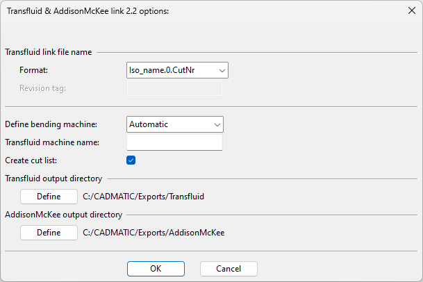
Define the settings:
Show/hide details
-
Format – Select how Transfluid files should be named:
-
Iso_name.0.CutNr
-
Iso_name-spool-Bend
-
Idn-spn2d-Bend-rev
-
-
Revision tag – If the naming format includes revision, enter the tag that contains the revision number.
-
Define bending machine – Select the machine type:
-
Automatic – This setting allows the machine type to be checked from the attributes of the bending machine: each bending machine should have an attribute whose tag is "bmc" and the value is either "TF" (for Transfluid) or "AM" (for Addison McKee). If the "bmc" tag does not exist or its value is not "TF" or "AM", then the user is always prompted to select the machine type of each file to be generated.
-
AddisonMcKee
-
Transfluid
-
-
Transfluid machine name – Enter the machine name to be shown in the "Machine" field of Transfluid files.
-
Create cut list – Select this option to generate cutting lists for straight (S_<listname>.pro) and bent (B_<listname>.pro) pipes.
The output location is …/<project>.pms/<user>.wsp/<area>.pm/docu.
-
Transfluid output directory – Click Define to select where Transfluid files should be output.
The default output location is …/<project>.pms/site/pi/Transfluid.
-
AddisonMcKee output directory – Click Define to select where Addison McKee files should be output.
The default output location is …/<project>.pms/site/pi/AddisonMcKee.
-
-
Click OK to accept the settings.
Configuration for single-spool export
Normally, the Transfluid & Addison McKee interface exports all spools of the selected isometric drawing.
You can set a separate export file to be created for each spool by adding the environment variable PI_TF_AM_SUB_MODE and the value "1" to one of the *.prf files such as:
…/stc/wsprofile/cadm_nt.prf
Example:
PI_TF_AM_SUB_MODE;1;Generating files
You can generate bending instructions and cutting lists for Transfluid or Addison McKee bending machines.
Prerequisites
-
Isometric drawing contains bent pipes that have cut numbers.
-
License for "Transfluid Interface" or "AddisonMcKee Interface".
-
"Transfluid Interface" was selected when installing CADMATIC.
-
Transfluid & AddisonMcKee link has been enabled in the options.
Do the following:
-
Do this if managing isometric drawings in Piping Isometrics & Spools:
Show/hide details
-
In the CADMATIC desktop, select the Piping Isometrics & Spools application and then Object > Run. The Isometric Drawings dialog opens.
-
Select one or more isometric drawings, right-click the selection, and select Exports > TF and AM link.
-
In Plant Modeller, on the Documents tab, click Piping isometrics. The Piping Isometrics dialog opens.
-
Select Drawings > Work with isometric drawings. The Isometric Drawings dialog opens.
-
Select one or more isometric drawings to be processed, right-click the selection and select Exports > TF and AM link.
Alternative method:
-
-
Do this if managing isometric drawings in Plant Modeller:
Show/hide details
-
Do one of the following:
-
On the Documents tab, click Piping isometric documents.
-
On the Piping isometric tab, click Manage.
The Manage Piping Isometric Drawings dialog opens.
-
-
Select one or more isometric drawings to be processed, right-click the selection and select Export > TF and AM Link.
-
-
If the settings for this interface have not been defined yet, the settings dialog opens. Define the settings as described in Defining link settings for isometric drawings.
-
If the interface is set to create cutting lists, a dialog opens for defining the header data:
Show/hide details
-
List name – Cutting list name.
-
Project no – Project number.
-
Yard – Yard name.

Enter the required information and click OK.
-
-
The files have been generated. You can close the open dialogs.